These instructions are based on our knowledge and opinions and offered for advice and guidance.
They are offered in good will but we accept no liability if you choose to use them.
General Fitting instructions for wood floors
A good quality Hardwood Flooring specialist would have many years of experience, in-depth knowledge of all aspects of hardwood floors including sanding and finishing and the correct tools to complete any type of installation. If you are investing large amounts of money on your materials you need to make sure the tradesman fitting for you has the knowledge and ability to carry out the work involved. This can only really be gained by years of experience working with wood. We would not expect a carpenter or joiner who does one or two installations of wood floor per year to be as good as those tradesmen who are laying floors constantly from week to week. Historically our apprentices would have had to work under supervision for at least a year or two before being allowed to work on their own for customers.
Ideal fitting environment
Prior to the work commencing all wet trades should be finished and the site should be closed and dry with the heating having been on. All new plaster, screeds etc should be dry. It is advisable for all other trades to be finished including decorating to insure that the new floor is safe from damage after installation from workmen and tools.The environment (humidity and temperature) to the rooms should be as close as possible to that expected when the building is occupied. The work area should be empty of all items apart from your tools and materials. Give some thought to floor protection while you are working and also for the remainder of works to follow before project completion.
Installation over a concrete or screed slab.
As a rule of thumb, it takes 4 weeks for the first inch of floor screed to dry, 4 weeks for the second inch of floor screed and 6 extra weeks for the 3rd inch. (i.e. 8 weeks drying time for a 2 inch screed and 14 weeks for a 3 inch screed). Cathedral Flooring can be successfully installed over a concrete or screed slab under certain conditions.The slab must be dry, flat and trowel finished. A trapped hygrometer test is a good way of testing the screed for the degree of dryness. Any damp or moisture source of any kind should be eradicated. All plumbing should be checked for leaks. Hot pipes below the new wood floor should be insulated. Sources of heat under the floor should be diffused if possible. Any pipe work unfinished should be pressure tested. Heating should be commissioned for at least two weeks before fitting commences.
The temperature and humidity of the building should be equal to the conditions of occupancy during and following the installation i.e. 40-55%. The existing floor surface should be flat with inaccuracies of not more than 3mm in a 2400mm span. If this is not follwed you may find that the floor bounces and does not sit flat. Providing this is not too bad it may eventually settle. The flooring to be laid must not be exposed to excessive periods of high humidity or moisture. After installation and during the first 2 months of occupancy the heating should be kept at a suitable level high enough to keep moisture levels low but low enough not to reduce the floors moisture content to rapidly as this may encourage distortion in the boards. It is essential that a suitable damp proof membrane exists and moisture tests are carried out before installation of the wood floor to ensure the screed is no more than 75% (ERH) equilibrium relative humidity as specified by British Standards.
Installation options for installing Cathedral oak flooring on under floor heating.
There are various methods of installing Cathedral Floors over under floor heating systems to take into account the type of heat source, expected operating temperatures and type of floor covering build up.
When installed over under floor heating Cathedral flooring must be fully bonded to a suitable substrate because: it works as a lateral tie to bond the individual boards together and in the case of floating floors reduces rotational movement at board joints to decrease movement and undulation when walked on.
The substrate ensures a greater area of bond to a sub floor by joining the boards together. The risk of separation from the screed is far greater for individual boards bonded to the screed. By bonding the boards to a sheet substrate and bonding the substrate down the risk of release is massively reduced by the larger overall contact area. In many cases where floors release from the screed it is found that the adhesive has not failed but the screed has separated from itself. Trying to take up individual boards to relay is very difficult. Normally as the problem boards are taken up other boards are loosened and you find yourself chasing your tail. The chance of a board 1200 x 2400 releasing is very slim but if it did the floor would still serve as a mass diaphragm-floating floor.
The substrate helps to disburse heat more evenly onto the floorboards and elevates hotspots, eliminates the possibility of convected air between joints which could lead to floor failure over time and acts to support header/butt joints of floorboards laid over joist, so there is no need to cut boards back to joist for support of header joints.
The substrate in length should be laid with staggered joints at 90º to the length of the Cathedral plank for the best lateral stability. This may however be impractical over joists.
The following options include relative calculations of output and energy efficiency.
Carpets and under floor heating
The maximum tog value of a carpet to be laid over under floor heating is 2.5 tog (0.25 w/m2k).
In a timber floor system R = 0.00 includes a layer of 18 mm chipboard and then the 2.5 tog carpet is allowed as an overlay. The total resistance of the carpet at 2.5 tog and the chipboard at 1.05 tog is 3.55 tog (0.355 w/m2k).
Fitting over UFH in screed
Option A:
6mm plywood bonded to screed with polyurethane adhesive. Cathedral 21 mm plank fully bonded to the plywood with D3 moisture resistant PVA. PVA is also required along the top of the tongues. Total resistance = 0.1588 W/m2k. 1.58 tog
Option B:
9mm plywood bonded to screed with polyurethane adhesive. Cathedral 21 mm plank fully bonded to the plywood with D3 moisture resistant PVA. PVA is also required along the top of the tongues. Total resistance = 0.1764W/m2k. 1.76 tog
Option C:
12mm plywood bonded to screed with polyurethane adhesive. Cathedral 21 mm plank fully bonded to the plywood with D3 moisture resistant PVA. PVA is also required along the top of the tongues. Total resistance = 0.1941 W/m2k. 1.94 tog
Option D:
15mm plywood bonded to screed with polyurethane adhesive. Cathedral 21 mm plank fully bonded to the plywood with D3 moisture resistant PVA. PVA is also required along the top of the tongues. Total resistance = 0.2117 W/m2k. 2.11 tog
Option E:
18mm plywood or chipboard bonded to screed with polyurethane adhesive. Cathedral 21 mm plank fully bonded to the plywood or chipboard with D3 moisture resistant PVA. PVA is also required along the top of the tongues. Total resistance = 0.2294W/m2k. 2.29 tog
Option F:
Fitting over UFH in batten or joisted floor Choose your substrate, 12mm plywood, 18 mm chipboard etc. The substrate and the Cathedral plank in length should be laid at 90º to the joist. The substrate should be laid with staggered joints. Screw the substrate to the batten / joist making sure that all joints are structurally supported and then fully bond the Cathedral floor to the substrate using PVA to bond wood to wood and Polyurethane to bond wood to Fermacell. Do not use liquid batten system. PVA is also required along the top of the tongues.
Option G:
Fitted over floated system UFH The substrate should be laid with staggered joints floated 90º to the desired direction of the Cathedral flooring. Float the substrate over the UFH and then fully bond the Cathedral floor to the substrate using PVA to bond wood to wood and Polyurethane to bond wood to Fermacell. Do not use liquid batten system.
Specification and design-Hardwood flooring
Under floor heating systems need to be well thought out in advance. Common mistakes at the design stage cannot always be rectified and can lead to substantial embarrassment and cost. If you are uncertain about any elements of under floor heating or Hardwood flooring we are only a phone call away. The heating design will leave certain areas of floor without heating such as under kitchen units, walk in larder, baths, showers, toilet pans, pedestals and under stairs cupboards. Bear in mind when redesigning after the heating has been installed that you may be having heating where it is not suitable and cold spots where floor space is exposed but not heated.
Existing buildings may need a review and most certainly upgrade of their current insulation to reduce heat loss on which calculations of output for the heating system will depend. In areas such as hallways and corridors where multiple heating circuits are on rout to their destinations it is necessary to insulate some of the heating pipes to reduce uneven heat build-up where the heat source is gathered. This is particularly required by the manifolds. This will ensure that all areas of the floor produce an even output which in tern produces more even expansion and contraction rates of the Cathedral flooring reducing problems that might otherwise occur.
BS EN1624 guideline figures for maximum floor temperatures are: occupied areas 29ºc, peripheral areas 35ºc and bathroom or similar 33ºc. Cathedral flooring has been tested 100% positive to withstand a variance of combined temperature in the same floor area exceeding the parameters of these figures. When fitted to our guidelines Cathedral flooring will withstand fluctuating moisture contents of 6.5% to 11%.
When installed over any type of under floor heating system it is critical that Cathedral flooring is bonded to a suitable substrate sheet. The purpose of the substrate is to strap the individual boards together for greater lateral stability and eliminate possible rotational force on individual boards.
This sheet also helps to disburse heat more evenly to the hardwood floor reducing hotspots and also eliminates any air from venting up between individual boards. The bond of the sheet material to the screed is much less likely to fail than individual boards but if it did the floor would still survive as a floating diaphragm. Many a time we have surveyed floor failure where the adhesive has kept its bond to the screed but the screed surface has failed. Trying to take up individual boards and re-bonding can be a nightmare as adjacent boards come loose in the process and you end up chasing your tail. We do not recommend bonding (CF) direct to screed even when UFH is not present.
Cathedral flooring 21mm 15 + 6 can be laid as a floating floor without a substrate only when UFH is not present. Cathedral flooring 21mm 15 + 6 must not be laid as a floating floor over under floor heating unless it is bonded to a suitable substrate which is floated or fixed down. The combined Cathedral flooring bonded to a wood substrate can be floated over UFH but the best option is a fixed down system. Until tests have been approved we do not advise to float Cathedral Flooring bonded to Fermacell over UFH “Dated 1.3.2002” Please check with supplier.
If the UFH design uses metal diffuser plates these must be in full contact with the overlaid floor for best efficiency. The best methods of using these plates are for them to be set in grooved ridged insulation. This helps to prevents them being damaged when walked on and ensures they are in contact with the underside or the floor covering. Some less expensive UFH designs have standard of the shelf insulation on which the pans rest. This leaves an air void under the plates, which we would not recommend. 25mm quilt insulation between the pans and the rigid insulation would help to eliminate some of this and support the pans to ensure they are in contact with the floor.
Another less expensive method of using plates is to nail then to joist or batten with rockwool slab or quilt beneath. Again air voids are present, not good. Often on site these plates get trod down and replacing them is not simple once the pipe has been laid. The result will be poor heat transfer, inefficient heating. A suitable underlay compatible with UFH can be installed between the plates and underside of the wood flooring to eliminate possible sound of the plates creaking against the flooring. UFH works best when all air gaps are eliminated and heat transfer is by direct conduction.
Air gaps present in a design rely on higher operating temperatures and only create low floor output temperature. If the air gaps are not totally sealed the heat can be vented out of the floor into cavities etc taking away any possibility to warm the floor. If air is allowed to vent up and between floor boards floor failure will surely follow owing the severe uneven drying of the boards. Underfloor heating in screed is at most risk during the screeding process.
It is important that the screeders are supervised to make sure the pipework remains where it was positioned to ensure the correct even output. If the pipe gets bunched up or randomly placed after coming free from its fixings the heating design will suffer. Wheelbarrows with poorly inflated tyres are not to be used. Photos of the laid pipe should be taken prior to covering. These can be compared to an infrared image at a later date if a problem is found with the floors performance. Any leaks can also be pinpointed by an infrared image.
Beware if a pumped screed is to be used (not to be mistaken for a flow screed). The pipe will deliver a bucket full of screed on each pulse. When the pump pulses its shear weight whips the pipe and can rip the heating pipe up in large sections. The screeders will not normally be too careful how they replace the pipe as long as it is covered. If they are made aware that is will be possible to see the placement of any disturbed pipe they will take more care.
An Anhydrite flow screed is the best option, incredibly fast to lay, faster drying and easy to level. This application is less likely to damage the pipework as long as the preparation work has been done to make sure the pipework does no float up.
After the heating system has been connected to the manifold the engineer will fill the system and prepare a pressure test to 6 bar. After confirmation that the installation is free of any leeks he will reduce the pressure to 3 bar and leave the system under test to be monitored during screeding.
Thermostats should be wired to floor probes to ensure the floors do not over heat causing damage to floor coverings. It is advisable to specify that a second floor probe is installed with each thermostat that can be wired in at a later date if the first probe fails. If the thermostats work on air temperature only the floor may be trying to heat more than one zone. If a connecting room with the door open is at a lower temperature or if an external window or door is left open. The result will be overheating of the floor.
It is important that from the start of any project the relevant trades and professional are made aware under floor heating is to be installed and the types of floor coverings intended. Details of intersecting floor coverings, finished floor levels and expansion provision need to be taken into account.
Site supervision and scheduling of works will play an important factor in the safe care and usage of the heating system, protection and performance of the floor coverings. Instruction on the correct use of the heating system should be passed on to the end user.
Scheduling the fitting of hardwood floors
It is essential that the heating system is covered either temporary or permanently as soon as possible for its protection. The hardwood flooring should be scheduled as a finishing trade as close as possible to the end of the project. If the floor is installed too soon it will be at risk from high moisture levels as well as damage by working practices of various trades. Traditional screed should be allowed 28 days and an anhydrite screed 21 days natural curing before heat is applied to assist drying.
Moisture tests can only be carried out on a cold screed, so time needs to be allowed for cooling and testing with the expectation that the heating and testing sequence will need to be done again. In practice it is fairly common that this is often left to the last minute when the Hardwood flooring installers arrive and the Architect is required to sign a disclaimer because the schedule is running out of time. The correct test is a surface hygrometer test to be carried out prior to the installer date.
The maximum (ERH) equilibrium relative humidity as specified by British Standards is 75%. The heating needs to be commissioned and working for at least 14 days prior to the installation of the wood floor. Thermostats need to be programmed at a temperature high enough to make sure that the floor is warm 24 – 7 and prevision of constant ventilation is required to prevent excess humidity in the building.
Concrete Base
It may be that the heating system and the hardwood floor are to be installed as a fully dry floated system straight over the top of the concrete base. It is important that this information is made clear to ensure that the concrete is put in flat and level. Normally the concrete is covered with screed and therefore the workman are not to particular with level and flatness because they expect the screed to give a finish floor level and not their concrete. A floated flooring system can only be laid parallel to the base it is laid over.
Calculations
Calculations should be obtained to access the room temperatures that will be achievable based on the type of heating installation combined with the chosen method of installing Cathedral plank flooring. As a precaution to protect the hardwood floor the heating system should be thermostatically controlled in all zones regulated by floor sensors so that the maximum permitted floor surface temperature is not exceeded. The industry standard is 27ºc, (CF) is 30ºc.
BS EN1624 guideline figures for maximum floor temperatures are: occupied areas 29ºc, peripheral areas 35ºc and bathroom or similar 33ºc. These temperatures would achieve an ambient air temperature of about 23ºc that would be far too uncomfortable for most people.Suitable
Substrate for Cathedral Oak Plank flooring
When installed over any type of Underfloor heating system it is critical that Cathedral flooring (CF) is bonded to a suitable substrate. We do not recommend bonding (CF) direct to screed. If the UFH system uses metal diffuser plates these must be in full contact with the overlaid floor for best efficiency. A suitable underlay compatible with UFH should be installed between the plates and underside of the wood flooring to eliminate possible sound of the plates creaking against the flooring.
Air gaps
We do not recommend using a UFH system that incorporates an air gap in its design in conjunction with (CF).
UFH works best when all air gaps are eliminated and heat transfer is by direct conduction. Air gaps present in a design rely on higher operating temperatures and only create low floor output temperature. If the air gaps are not totally sealed the heat can be vented out of the floor into cavities etc taking away any possibility to warm the floor. If air is allowed to vent up and between floor boards floor failure will surely follow owing the severe uneven drying of the boards. We have surveyed installations where this advice has been ignored and the heating systems were found to be totally inefficient causing the requirement for secondary heating systems to be installed.
Floating Floors
Cathedral Flooring 21mm 15+6 floors can be laid as a floating floor without a substrate only when UFH is not present. They must not be installed as floating without firstly being bonded to a suitable substrate, and only form a structural floor once bonded to a substrate. Cathedral Flooring can be laid as a floating floor without a substrate only when UFH is not present.The combined Cathedral floor bonded to a wood substrate can be floated on Underfloor heating but the best option is a totally fixed down system. UFH works best when all air gaps are eliminated and heat transfer is by direct conduction.
Moisture conditions
Moisture tests can only be carried out on a cold screed. The correct test is a surface hygrometer test to be carried out prior to the installer date.
The maximum (ERH) equilibrium relative humidity as specified by British Standards is 75%. The heating needs to be commissioned and working for at least 14 days prior to the installation of the wood floor. Thermostats need to be programmed at a temperature high enough to make sure that the floor is warm 24 – 7 and prevision of constant ventilation is required to prevent excess humidity in the building.
Wood floor thickness and heat resistance over UFH The maximum resistance floor covering with a boiler feed system is 2.5 tog – 0.25 W/m2k. The lower resistance the better the performance and energy efficiency of the heating system. At this higher limit the operating temperature of the floor needs to be as high as 55ºc.
With ground source or air to water heat exchangers the highest operating temperatures achievable are 41ºc at a push. This means that the resistance of the floor covering needs to be kept to a minimum. Fermacell (Gypsum fiber board) is the desired substrate to be used in this situation due to its low resistance. (There are on site difficulties with the use of `Fermacell due to the fact that it can not be walked on unless fully supported, so over joist etc crawl boards will be required).
In the event that CF needs to be raised above a screed to obtain corrected levels Fermacell may be the only product suitable to built up in layers, as a substrate to minimise the resistance calculations. Fermacell has an advantage of being laid at a thickness of 205.5% more than wood. The resistance of 20 mm of wood is equivalent to 41.1 mm of Fermacell.
On site protection of hardwood flooring
The hardwood flooring should be installed as close as practicable to the end of a project.
The hardwood floor should be protected after installation from moisture conditions and working practices. It is best to use good supervision and temporary covering in working areas. Clean dustsheets and hardboard should be used carefully and then cleared between jobs to expose the floor. This will encourage respect of the floor and highlight any damage as well as the persons responsible.
Selected persons who are aware of safe operating temperatures and procedures for the hardwood floor should be the only ones authorised to adjust settings.
Permanent boarded covering may cause condensation and damage the floor. Any dust, grit fixings etc that may find their way under the boarding will go unnoticed until close to hand over and could cause severe damage.
Expansion
As with all wood flooring, provision for expansion should be allowed. Expansion should also be considered in the screed especially when UFH is present. Because timber expands at a far greater rate across the grain rather than in the length it is good practice to lay the floor in the longest direction of the room. It also looks better this way. An expansion gap must be maintained around the perimeter of each room – doorways – any abutted hard surface – obstructions passing through the floor such as radiator pipes.
Intersection of hardwood floors and stone
Expansion is required here. This can be achieved by keeping the wood surface 7mm above the stone and rebating it to overall the stone with an expansion gap out of sight. Many designers and Architects want the stone and wood on one level which requires the expansion joint to be visible and the use of a third material to fill the gap.
This often looks unsightly, especially after time.
Setting out
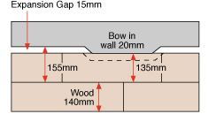
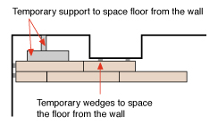
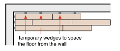
Fig.1
Fig.2
Fig.3
Do not worry! If the wall is not straight, set out a start line the width of the boards + the width of the expansion gap minus the depth of the most protruding part of the wall. e.g. Board width is 140mm and the expansion gap is 15mm (140mm + 15mm = 155mm) and the protruding part of the wall is 20mm (155mm – 20mm = 135mm) the start line should be no more than 135mm from the most protruding part of the wall. Some of the infill boards will now fit into place leaving the expansion gap and some will need to be scribed into place (shaped into place). (Fig 1). Use short lengths of board to space the floor from the wall so that the floor is supported as you fit it together. Lay 3 runs up and down the line and leave for 30 minutes for the glue to set before continuing if you are laying as a floating floor. This forms a solid panel which stops the floor from coming apart when you really get going.
Sometimes there may not seem to be an obvious place to start. For instance there might be a hearth to a fireplace in the way (Fig 2). This really does not matter because where ever you start it is possible to brace off the walls to support the laying of the floor and then work backwards to the walls afterwards. To reverse lay a secret fixed floor you will need loose tongues.
If the room is square and the walls are straight then lay 3 runs (as described earlier) and use wedges to hold the floor 15mm away from the walls to allow for the expansion gap. (Fig 3)
Tools and equipment
Trade and professionals – those who want to be. Chop saw, Jig saw, Fein cutter, Router, Electric tenon saw, Screw guns, Pistol drill, 4” belt sander, Orbital sander, Porter nailer, Biscuit cutter, Strap clamps, Draw bar, Hand saw, Skil saw, Tape measure, Hammer, Square, pin punch, Chisels, Drill bits, Vacuum cleaner.
DIY Jig saw, New sharp hand saw, T Square, Power drill, Hammer, Pin punch, Tape measure, Strap clamps, Orbital sander, Pencil, Screw drivers, 12mm chisel.
General fitting guidelines
The floor must be scraped and swept clean. Check the floor for flatness before commencing to establish any high spots. In the cases of badly uneven floors. Latex self levelling screed may be needed to level the floor. If this is not follwed you may find that the floor bounces and does not sit flat. Providing this is not too bad it may eventually settle.
Preparation Work
Expansion; Timber expands and contract due to changes in humidity. For this reason it is necessary to allow expansion gaps to the perimeter of timber floors and some times within the floor itself. To be on the safe side10mm expansion per 1m run across the boards is required. This means that a 3m wide room will have 30mm of expansion allowance. Although timber expands and contracts far greater across the grain than it does along the grain there should still be expansion to the ends of the floor. Expansion gaps should be left clear. Do not fill them with cork. In theory, (given the average domestic width of room at 3.5m wide) if you could physically sit in the centre of the finished floor and move it, you should be able to move the floor in any direction 15mm. This means that any obstructions such as radiator pipes which pass through the floor should have expansion around them. Although Cathedral Flooring is so much more stable than natural flooring we still recommend that you follow the fitting guidelines herein. Expansion can be built into the width of the floor by laying with washer gaps between the boards if the need arises. (Fig 4). In the case of Cathedral Flooring this is for appearances rather than necessity.
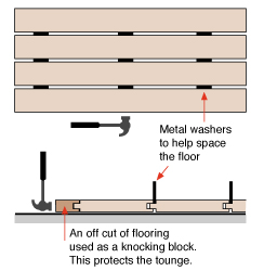
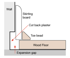
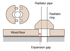
Fig.4
Fig.5
Fig.6
It is sometimes required to remove skirtings and cut back plaster or dry lining to allow extra expansion. (Fig 5)
The normal expansion allowance around radiator pipes is 15mm because the cover rings need to cover the gap. (Fig 6)
It is important to check around the radiator pipes periodically to make sure the floor does not expand onto them. It may be required to ease the floor in front of them to allow further expansion in time. Insulate any hot water pipes that run under the floor.
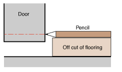
Fig. 7
Mark doors for cutting to length before removing them.
Place an off cut of the flooring to the base of the door and hold a pencil flat to the face. (Fig 7) Mark the door all the way across. Repeat this with the door in different opening positions. This should give you a clearance cut line about 4 – 5mm above the new finished floor level. Now remove doors and set aside ready for cutting.
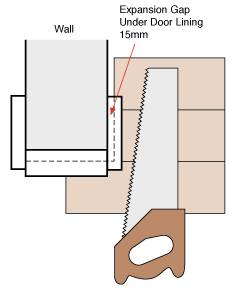
Fig. 8
Undercut door linings to allow free movement for expansion.
Expansion must be allowed under door linings. (Fig 8) Place an off cut of flooring at the base of the lining flat to the floor. Holding a sharp saw flat to the face off the off cut cut the lining and architrave and also 45mm of the abutting skirting if it is existing. Professionals might use a fein cutter or electric tenon saw to make this task quicker and easier. Remove the timber beneath the saw cut with a very sharp chisel. Sometimes it is necessary to nibble away the corner of the studwork or masonry behind the lining to achieve a full 15mm expansion gap.
Sub-floor condition
The work area must be completely clear of obstructions. The floor must be scraped and swept clean. Check the floor for flatness before commencing to establish any high spots. In the cases of badly uneven floors latex self levelling screed may be needed to level the floor.
Underlay and D.P.M
An underlay must be installed between the wood floor and sub-floor and must also wrap up the wall to protect the edge of the floor. This acts as an insulator and buffer. This must be sealed at all joints with a moisture resistant tape. On any ground floor a damp proof membrane (DPM) must be used with 200mm overlaps sealed with tape also and turned up the wall. It is best to lay the insulation first and then the D.P.M. This way any possible condensation will be decreased. Alternatively use an underlay with a built in DPM and tape all joints.
A Floating Floor
A floating floor is a floor that is laid over a existing timber or solid floor without being mechanically fix down, eg nailed or screwed.The floor is fixed together in such a way that it becomes one big sheet and is held down by its own weight.When using solid Hardwood flooring it is advisable for the boards not to exceed 100mm in width as wider boards are more likely to cup. If wider boards are preferred a fix method of installation is needed. This is obviously not necessary when using Cathedral Flooring.
An expansion gap must be maintained around the perimeter including under door linings etc to allow for expansion. An expansion gap must also be allowed around any radiator pipes etc which pass through the floor.If the floor is restricted from expanding it will raise and become springy.This expansion gap is covered when the skirtings or beads are fixed. Boards can be fixed together by gluing the top of the tounge and the bottom of the groove (Fig 9) or by screwing or nailing to a batten which itself is not fixed down (Fig 10).
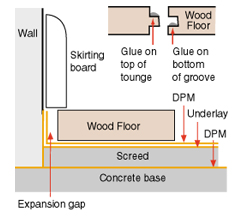
Fig. 9
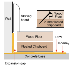
Fig. 10
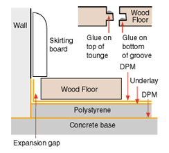
Fig. 11
Floating Floor
Lay the floor by gluing together all four edges. Apply the glue to the top of the tounge and the bottom of the groove. (Refer to setting out)
Some times you may have difficulty pushing the boards together due to a vacuum being caused in the groove by the glue trapping in air. To stop this from happening apply 200mm lines of glue with 25mm gaps between them. This will allow air to escape and then the glue will spread along the gaps.
If the glue squeezes out on top of the floor you may be using to much glue, but be sure to use enough. Lay 3 runs and leave for 30 minutes for the glue to set before continuing. This forms a solid panel which stops the floor from coming apart when you really get going. Strap clamps are very useful for pulling the boards tightly together. Check that the butt joints are tight. A pull bar is useful for tapping up the last board. (Fig 12)
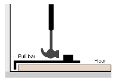
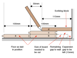
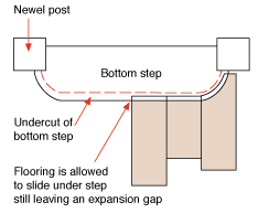
Fig. 12
Fig. 13
Fig. 14
If possible work with the tongues pointing towards you. When tapping up the boards use an off-cut of flooring between the hammer and the tongue to stop the tongues from being damaged. If the tongues become damaged it will be necessary to remove the damaged part with a sharp chisel. If you hammer against the groove side of the board and cause damage you will have to discard that board.
Make sure you stagger the header joints of the boards for the best appearance. Try not to get too many header joints in line as you look across the floor. The closest the header joints should be is twice the width of the boards. For ease of sanding make sure the header joints are at least 200mm away from the walls on the ends of the boards.
Method of cutting scribes / infills to walls
A and B are the last two full width boards laid (Fig 13). Place a spare board c on top of b so that it lines up perfectly in width. Using a piece of flooring cut to length 15mm longer than the width of the boards and held against the wall mark board c to be cut. e is the face width of the piece of flooring that when laid in the remaining gap will leave a 15mm parallel expansion gap. The scribing block d is always cut – the width of the flooring + the expansion gap required.
Stair scribe
Don’t forget to allow expansion to the bottom of stairs by under cutting the bottom step. (Fig 14). The load on the bottom step will rest on and be transposed through the hardwood floor to the subfloor or packing shims.
Joints between doors
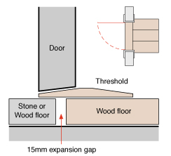
Fig.15
Door opening between two wood floors with dividing expansion joint from stone to wood or wood to wood.
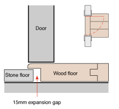
Fig. 16
Door opening onto wood floor away from stone or tile. (Fig 16)
The floor must be separated by an expansion gap between rooms to allow each area to move freely. (Fig 15) If this is not done the compounding expansion may cause problems. The expansion can be covered by a surface threshold fixed to one floor only and held down by the door stops.
Wide floors and expansion – secret fixed floors.
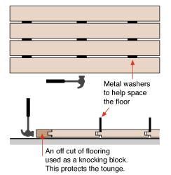
Fig. 17
Sometimes there is the need to allow for expansion within the width of the floor because the perimeter expansion allowance will not be enough. (Fig 17). This can be achieved by using washers to space the boards as they are laid. It is advisable to leave the washers in for a few rows and bring the back row forward as you add moor boards. This stops the gaps closing up as you tap up the new rows.
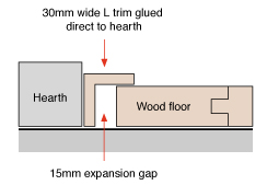
Fig. 18
Expansion around hearths
Expansion is required to fire hearths.
The method used has to depend on the type of hearth and how best to achieve the right appearance. Sometimes fitters cut the floor within 2 mm of the hearth and leave the gap as a shadow gap. This reduces the amount of expansion so it might be necessary to recut at a later day if there is a problem. The customer needs to be aware of this.
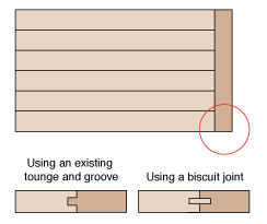
Fig. 19
Methods of jointing end boards, thresholds etc to the floor.
Usually required in doorways (Fig 19).
Fittings
If you are using solid wood flooring or have solid wood supplied for thresholds many types of fitting can be made from the flooring section you are using (Fig 20). If you are using the Cathedral range of flooring the choice is more limited but fittings made from solid wood of the same type will match. Shop bought fitting are OK but fittings made from the material you are using are an exact match and can be made to suit any detail. It is sometimes necessary to biscuit joint the fittings to the floor as the existing tongue and grooves on the sections will not work in some cases. Threshold details depend on the adjoining floor types. Each doorway has to be considered individually according to how the floor intersects it.
If you are using a pre finished coloured floor it might not be possible to match the colour so you may have to find a way of making any fittings you need from the floor you are using.
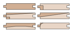
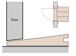
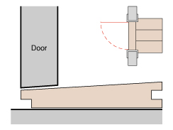
Fig. 20
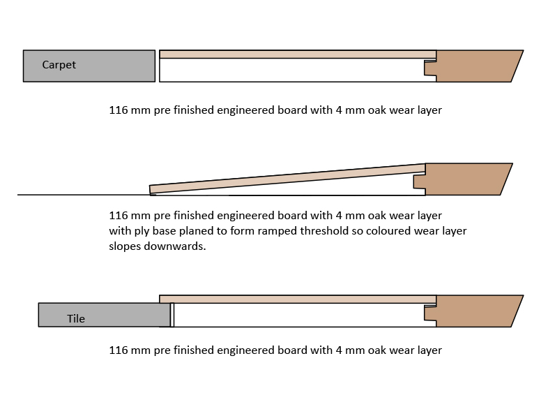
Profiles you can achieve
Fig. 21
Door opening away from wood floor onto Lino or other low level surface.
Fig. 22
Door opening away from wood floor onto carpet or tile etc.

Fittings for special pre finished coloured floors.
Its relatively simple to make and finish Oak sections with clear finishes but when it comes to factory special finished floors it will be very difficult to colour match any fittings you make. For this reason you should try to make fittings out of the floor being used so you keep the . pre finished surface. When it comes to trim and skirtings you would be wiser using a painted colour to compliment the floor.
Expansion gaps
After the flooring has been laid and sanded, the expansion gaps need to be concealed. The way this is achieved depends on the width of the gap. In some cases a skirting will do fine (Fig 23). Sometimes the skirtings are existing and a toe bead can be used. (Fig 24) The advantage of a toe bead is that it is simple to remove without causing damage to decoration and therefore if over expansion of the floor occurs the floor can be simply trimmed without too much hassle. If skirting have to be removed they sometimes have to be replaced due to damage in getting them off and re- decoration will be required. In some instances as showed above it will be necessary cut back plaster work and use both skirting and toe bead to allow maximum expansion. (Fig 25)
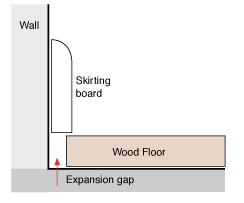
Fig. 23
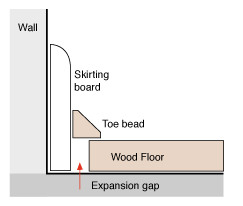
Fig. 24
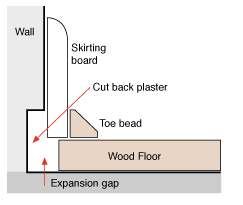
Fig. 25
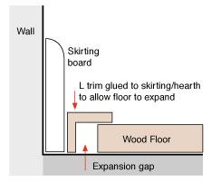
Fig. 26
Stairs and steps
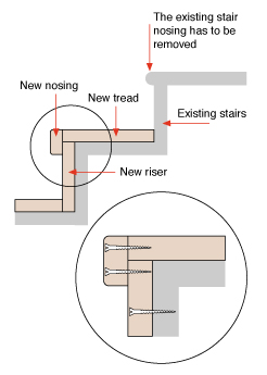
Fig. 27
In some instances existing stair treads and risers can be covered to match the hardwood flooring. Fig. 27 shows a makeshift method used by many.
Cathedral Flooring can supply stair sets that have a much better detail. Ask for details.
When the nosing is removed the structure of the stair is weakened. For this reason it is very important that the new riser is glued and pined to the old riser and the end of the old tread. The new nosing is then pined and glued to the new tread and riser as shown. (Fig 24) The structure is then re-strengthened.
Fittings between levels
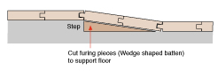
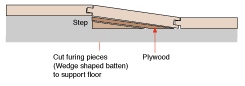
Fig. 28
Fig. 29
Finishing to exterior door thresholds opening out
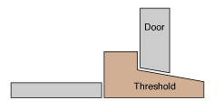
Fig. 30
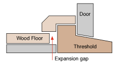
Fig. 31
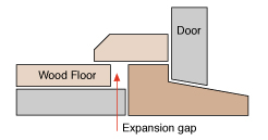
Fig. 32
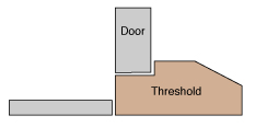
Fig. 33
Fig. 34
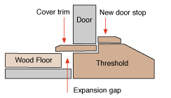
Fig. 35

Fig. 36
Finishing to radiator pipes
Expansion gaps around radiator pipes are covered by radiator rings. These come in two halves which are pushed together onto the pipe and connected by small dowels.
Mat Wells
Various methods of fitting mat wells. If you put a coir mat in the well this can be bought in up to 1.5 m wide rolls in any length. Then cut to fit. You will find that the surface of the mat will be the same as your floor. (Fig 37)
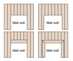
Fig. 37
Fixed Floors
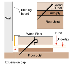
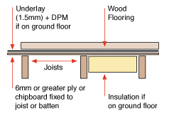
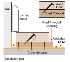
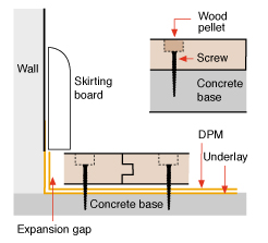
Fig. 38
Fig. 39
Fig. 40
Fig. 41
You can fix direct to joists (Fig 38 & 39). However a minimum of 9 mm ply as an intermediate layer is required to support the butt joints of the boards which may land between joists. A better option is to use 18 mm chipboard as this may be cheaper, but remember to consider the thickness build up. The ply is required to be fixed to the joists. If you do not use ply you should cut ends of floor boards to land on the joist for structural support. This increases the wast factor of the flooring and cost.
By installing plywood sheets or chipboard over the joist first you enable the other trades (plasters, decorators etc) to complete there work quicker and safely prior to the hardwood floor being installed. The absence of the need to cut the lengths of flooring back to the joist supports means a greatly reduced waste factor in the use of the floor. Make sure the plywood is of suitable quality as cheap plywood is prone to de-lamination.
For a fixed down floor over screed it is possible to fix your ply sheets direct to the screed and then fix your floor to the ply (Fig. 40).
Floors can also be screwed and plugged direct to the screed. The advantage of this is that it saves the height (Fig 41). But it is very time consuming. Not for the faint hearted.
Under Floor Heating
Cathedral Flooring has been proved to work with underfloor heating. Unfortunately a guarantee can not be offered for its use in this situation due to reasons which are beyond the control of the supplier and fitter. If a dispute arises there is no reliable way of recording or monitoring the under floor heating system settings or room conditions over a period of time. Because of this it is impossible to prove or disprove how the system had been used or abused by the customer. Development tests over time have proved that Cathedral Flooring out performs traditional solid hardwood floors and block board core products when used with under floor heating.
This is due to the structural characteristics of ply wood. Ply wood is probably the most stable wood product available on the market todate. Due to the construction of Cathedral Flooring it conducts heat whilst keeping its stability much better in comparison to traditional solid or other engineered flooring. If Cathedral Flooring is fitted in accordance with the guidelines of the under floor heating companies instructions then the floor will eventually reach an equilibrium within the room. This is where the temperature and relative humidity levels are maintained within a fairly consistent range.
It is best if the screed is dried naturally – the under floor heating should not be turned on before the correct moisture level is achieved. If you turn the heating on to dry the screed out you may find that it will crack. The sub floor must be heated before the wooden flooring is laid. This heating up has the sole purpose of allowing any residual moisture which may be present within the screed or have formed to escape from the cement floor. Heating up the of new cement floors should be commence at the earliest 21 days after they have been laid, the procedure being that the flow temperature of the heating is increased by a maximum of 5°C per day until the maximum temperature is reached. This is to be maintained for 6-7 days and not reduced at night.